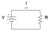
Ohm's law shows a linear relationship between the voltage and the current in an electrical circuit.
The resistor's voltage drop and resistance set the DC current flow through the resistor.
With water flow analogy we can imagine the electric current as water current through pipe, the resistor as a thin pipe that limits the water flow, the voltage as height difference of the water that enables the water flow.
The resistor's current I in amps (A) is equal to the resistor's voltage V in volts (V) divided by the resistance R in ohms (Ω):
V is the voltage drop of the resistor, measured in Volts (V). In some cases Ohm's law uses the letter E to represent voltage. E denotes electromotive force.
I is the electrical current flowing through the resistor, measured in Amperes (A)
R is the resistance of the resistor, measured in Ohms (Ω)
Voltage calculation
When we know the current and resistance, we can calculate the voltage.
The voltage V in volts (V) is equal to the to the current I in amps (A) times the resistance R in ohms (Ω):
Resistance calculation
When we know the voltage and the current, we can calculate the resistance.
The resistance R in ohms (Ω) is equal to the voltage V in volts (V) divided by the current I in amps (A):
Since the current is set by the values of the voltage and resistance, the Ohm's law formula can show that:
If we increase the voltage, the current will increase.
If we increase the resistance, the current will reduce.
Example #1
Find the current of an electrical circuit that has resistance of 50 Ohms and voltage supply of 5 Volts.
Solution:
V = 5V
R = 50Ω
I = V / R = 5V / 50Ω = 0.1A = 100mA
Example #2
Find the resistance of an electrical circuit that has voltage supply of 10 Volts and current of 5mA.
Solution:
V = 10V
I = 5mA = 0.005A
R = V / I = 10V / 0.005A = 2000Ω = 2kΩ
Ohm's Law for AC Circuit
The load's current I in amps (A) is equal to the load's voltage VZ=V in volts (V) divided by the impedance Z in ohms (Ω):
V is the voltage drop on the load, measured in Volts (V)
I is the electrical current, measured in Amps (A)
Z is the impedance of the load, measured in Ohms (Ω)
Example #3
Find the current of an AC circuit, that has voltage supply of 110V∟70° and load of 0.5kΩ∟20°.
Solution:
V = 110V∟70°
Z = 0.5kΩ∟20° = 500Ω∟20°
I = V / Z = 110V∟70° / 500Ω∟20° = (110V / 500Ω) ∟ (70°-20°) = 0.22A ∟50°
Ohm's Law Calculator (short form)
Ohm's law calculator: calculates the relation between Voltage, Current and Resistance.
(A) lack of oil (B) belt too tight (C) armature not centred with respect of pole pieces (D)bearings too tight or not in line
What causes heating of armature?
(A) eddy currents (B) moisture which almost short-circuits the armature (C) unequal strength of magnetic poles (D) Operation above rated voltage and below normal speed.
How may the direction of rotation of a DC motor be reversed?
This can be done by reversing either the field current or current through the armature. Usually, reversal of current through the armature is adopted
What happens if the direction of current at the terminals of a series motor is reversed?
It does not reverse the direction of rotation of motor because current flows through the armature in the same direction as through the field
What will happen if a shunt motor is directly connected to the supply line?
Small motors up to 1 KW rating may be line-started without any adverse results being produced High rating motors must be started through a suitable starter in order to avoid the huge starting current which will – Damage the motor itself – Badly affect the voltage regulation of the supply line
A DC motor fails to start when switched on. What could be the possible reasons and remedies?
Open-circuit in controller-should be checked for open starting resistance or open switch or open fuse
Low terminal voltage-should be adjusted to name-plate value.
Overload-should be reduced if possible otherwise larger motor should be installed.
Excessive friction-bearing lubrication should be checked.
Why does a DC motor sometime run too fast when under load? Give different possible causes and their remedies.
Different possible causes are as under:
Weak field-remove any extra resistance in shunt field circuit Line voltage too high-reduce it to name-plate value Brushes back of neutral-set them on neutral
What causes are responsible for over-heating of Commutator in a DC motor?
It could be due either to the brushes being off neutral or being under excessive spring pressure. Accordingly, brushes should be adjusted properly and the spring pressure should be reduced but not to the point where sparkling is introduced
How is magnetic leakage reduced to a minimum in commercial transformers?
This is done by interleaving the primary and secondary windings
Mention the factors on which Hysteresis loss depends?
Quality and amount of iron in the core Flux density Frequency
How do changes in supply voltage and frequency affect the performance of an induction motor?
High voltage decreases both power factor and slip, but increases torque. Low voltage does just the opposite. Increase in frequency increases power factor but decreases the torque. However, per cent slip remains unchanged. Decrease in frequency decreases power factor but increases torque leaving per cent slip unaffected as before
What is, in brief, the basis of operation of a 3-phase induction motor?
The revolving magnetic field which is produced when a 3-phase stator winding is fed from a 3-phase supply
Why induction motors are called asynchronous?
Because their rotors can never run with the synchronous speed
Enumerate the possible reasons if a 3-phase motor fails to start?
One or more fuses may be blown Voltage may be too low The starting load may be too heavy Worn bearings due to which the armature may be touching field laminae, thus introducing excessive friction
A motor stops after starting i.e., it fails to carry load. What could be the reasons?
Hot bearings, which increase the load by excessive friction Excessive tension on belt, which causes the bearings to heat Failure of short cut-out switch Single-phasing on the running position of the starter
Which is the usual cause of blow-outs in Induction motors?
The most common cause is single-phasing
Can a 3-phase motor be run on a Single-Phase Line?
Yes, it can be. But a Phase-Splitter is essential
What is a meant by a Phase-Splitter?
It is a device consisting of a number of capacitors so connected in the motor circuit that it produces, from a single input wave, three output waves which differ in phase from each other
What is the standard direction of rotation of an Induction motor?
Counter clock wise, when looking from the front end i.e. non-driving end of the motor
How would you reverse the direction of rotation of a capacitor start-induction-run motor?
By reversing either the running or starting-winding leads where they are connected to the lines. Both must not be reversed
What could be the reasons if a split-phase motor fails to start and hums loudly?
It could be due to the starting winding being open or grounded or burnt out.
What could be the reasons if a split-phase motor runs too slow?
Wrong supply voltage and frequency Overload Grounded starting and running windings Short-circuited or open winding in field circuit
What are the two types of turbo-alternators?
Vertical and horizontal
What is direct-connected alternator?
One in which the alternator and engine are directly connected. In other words, there is no intermediate gearing such as belt, chain etc. between the driving engine and alternator
What is the difference between direct-connected and direct-coupled units?
In the former, alternator and driving engine are directly and permanently connected. In the latter case, engine and alternator are each complete in itself and are connected by some device such as friction clutch, jaw clutch or shaft coupling
Can a generator be converted into an alternator?
Yes, by providing two collector rings on one end of the armature and connecting these two rings to two points in the armature winding 1180 apart
For what service are synchronous motors especially suited?
They are especially suited for high voltage service
Which has more efficiency; synchronous or induction motor?
Synchronous motor
Mention some specific applications of synchronous motors
constant speed load service reciprocating compressor drives power factor correction voltage regulation of transmission lines
What is a synchronous capacitor?
An over excited synchronous motor is called synchronous capacitor, because, like a capacitor, it takes a leading current
What could be the reasons if a synchronous motor fails to start?
Voltage may be too low Some faulty connection in auxiliary apparatus Too much starting load Open circuit in one phase or short circuit Field connection may be excessive.
Under which conditions a synchronous motor will fail to pull into step?
No field excitation Excessive load Excessive load inertia
Do stepper motors have internal or external fans?
No, because the heat generated in the stator winding is conducted through the stator iron to the case which is cooled by natural conduction, convection and radiation
Any disadvantage of having more phases?
More leads have to be brought out from the motor More interconnections are required to the drive circuit More switching devices are needed.
Will there be any harm if the rotor of a hybrid stepper motor is pulled out of its stator?
Yes. The rotor will probably become partially demagnetized and, on reassembling, will give less holding torque
What are the advantages and disadvantages of Compact Fluorescent Lamps?
CFLs are up to four times more efficient than incandescent bulbs While initially they may cost more, CFLs are less expensive in the long run as they last much longer than incandescent bulbs CFLs are highly versatile and can be used in any setting that you would normally use incandescent bulbs The disadvantages are
CFLs when used outdoors need to be covered and protected from the elements. They are also sensitive to temperature While CFLs are supposed to last about 10,000 hours, turning them on and off too frequently can reduce that lifetime substantially CFLs are not suitable for focused or spot lights or where narrow beams of light are required. They are meant only for ambient light. Give an example of integrating instruments
Can a series motor be started without any load?
No, because if a DC series motor is started without load, the armature winding (winding that doesn’t spin) current will be at a minimum, resulting in the motor going to maximum speed / runaway, which can cause things to fly apart. As Armature current increases, the speed of the motor will decrease. The armature current will be forced to increase / speed of the motor will be forced to decrease as more and more load is applied
Are single phase induction motors self-starting?
In single phase induction motor, there is no self starting as initially torque is zero. but we can make it self-stating by adding an extra winding known as starting or auxiliary winding and space the two by 90 degrees. Due to this, the two currents will produce revolving flux what will make the induction motor self starting
PLC
Question 1. What is PLC?
Answer: PLC is the short abbreviation of Programmable Logic Control.
PLC is a solid-state control device or computerized industrial controller that performs discrete or sequential logic in the automation industry.
PLC is a combination of software and hardware. It acts as the brain of the machine or system for automation control systems.
PLC is a digital electronic device that performs the following basic tasks.
uses programmable memory to store instructions
implement specific functions such as programming logic, sequence, timing, counting, and arithmetic operations
control electronic machines and technical process
Question 2. Who is the father of PLC?
Answer: Dick Morley is called as the father of the programmable logic controller (PLC).
In 1968, under his study, he has created and developed the first industrial PLC i.e. Midcon PLC. The first Midcon PLC is built for General Motors.
Question 3. What is the role of PLC in Automation?
Answer: In automation, PLC is playing a significant role in controlling and monitoring industrial applications.
It has both hardware and software.
This controller device can be executed or operated by automatically and manually. For its operation, it consumes additional manpower, time, utility, and accurate operation in the system.
It is useful for increasing the reliability and stability of the system.
It performs precise operations within very less time. This is one of the reasons, today, PLC is widely used in the industry.
Question 4. What are the different components of PLC?
Answer: PLC has different components. Each component has associated with specific PLC operations and functions.
Here is the list of the useful basic components –
Input and Output modules These modules provide input to the PLC and yield output. Input and output can either be digital or analoge types.
Power Supply This component is responsible for providing AC or DC power supply to operate PLC.
Central Processing Unit (CPU) CPU stores and execute PLC software programs.
Memory System As the name depicts, the memory system is responsible for storing and retrieving information required for PLC operations.
Communication Protocol There can be multiple devices connected to PLC. Communication protocols are used for exchanging information from one device to another.
PLC Programming (Software skill) You need to write a programming language to implement PLC logic.
These are the six basic components of the PLC.
Question 5. What are the types of PLC?
Answer: There are two basic types of PLC based on the construction and working of PLC.
Compact PLC
Modular PLC
Questions 6. What are the different PLC brands?
Answer: The various companies are invented their own PLC brands. Here are some popular PLC brands.
ABB PLC
AB (Rockwell) PLC
Siemens PLC
Delta PLC
Mitsubishi PLC
Honeywell PLC
Omron PLC
Schneider PLC
Hitachi PLC
Fatek PLC
Bosch PLC
GE (General Electric) PLC
Siemens PLC and Allen-Bradley (AB) PLC are mostly used for project and educational purposes.
Question 7. Explain the difference between Compact and Modular PLC?
Question 7: What is the block diagram for Compact and Modular PLC?
Compact PLC block diagram:
Modular PLC block diagram:
Question 8. What are the different programming languages used in PLC?
Answer: The programming language is used to create the program to control the PLC or automation system.
As per the IEC standard, five different types of programming languages are used in PLC.
The list of different PLC languages used in the industry is as follows.
Ladder Diagram (LD)
Instruction List (IL)
Structured Text (ST)
Function Block Diagram (FBD
Sequential Function Charts (SFC)
Question 9. What is LD in PLC?
Answer: LD is the short abbreviation of the “Ladder Diagram”. It is the most popular and universally accepted programming language for PLC.
It is easy to implement PLC logic with LD as it provides a graphical user interface.
LD is known as “Ladder Diagram Language” or “Ladder Logic Language”.
Question 10. What is rung?
Answer: In LD programming, the numbers of the horizontal lines are represented as the “rungs”.
Question 11. What is the timer?
Answer: Timer is the most essential instruction for PLC. The timer is used to operate and control devices for a specific duration of time. The programmer can set the timer based on the project requirement.
Question 12. What are the different types of PLC timers?
Answer: In general, there are three different types of timers used.
On Delay Timer
Off Delay Timer
Retentive On Timer (RTO)
Question 13. What is the function of the RTO?
Answer: RTO is a Retentive On Timer. The main function of the RTO is used to hold or store the set (accumulated) time.
Question 14. What is the counter?
Answer: Counter is an instruction which is useful for sequential counting as digital numbers. It is part of the mathematical function.
Question 15. What are the different types of counters used in PLC?
Answer: The PLC counter is classified into three different types.
Up Counter
Down Counter
Up/Down Counter
In PLC programming, the up/down counter is mostly used.
Question 16. What is the rack or chassis?
Answer: The modular PLC consists of a number of input or output modules, the controller processor, and the communication controller. This hardware assembly of these modules is called as “Rack or Chassis”.
Refer modular PLC block diagram mentioned in an earlier question.
Question 17. What is the PLC Scan Cycle?
Answer: When the PLC program is executed, there are multiple repetitive processes occurred. This is entire process is called a PLC scan cycle.
This scanning program consists of reading input data, executing the programming logic, and updating the output data in one cycle.
The scan time is the time required for continuously scanning programs. It takes approximately 10ms-15ms of time.
Question 18. What is the standard format for the digital I/O module address used in the AB PLC program?
Answer: The format for the digital I/O address is as below.
File type: Slot Number. Word Number/ Bit Number
This is the standard addressing format used in AB PLC’s brand.
Question 19. What is the MCR?
Answer: MCR is the short abbreviation of “Master Control Relay”. It is a type of instruction used in Siemens PLC software. This instruction is used to shut down the process.
There are some other types of MCR instruction like
MCRA (Master Control Relay Active),
MCRD (Master Control Relay Deactive),
MCR< (Master Control Relay Less),
MCR> (Master Control Relay Greater).
Question 20. What is Communication Protocol?
Answer: The system communicates with two or more communicating devices for transferring digital data or information. This communication is governed by some set of rules called as ‘Communication Protocol’.
The standard definition 0f communication protocol is a set of rules that govern data communication.
You can expect multiple PLC interview questions related to the communication protocol.
Question 21. What are the different types of communication protocols used in PLC?
Answer: In the PLC communication network, various types of protocols are used for communicating with multiple connected devices.
Here are some standard PLC communication protocols.
Recommended Standard (RS-232, RS- 422, and RS-485) Protocol
These are the foremost communication protocols used for the PLC and other network connections. These protocols are supported by different PLC software brands.
The communication protocols are dependent upon three fundamental parts such as baud rate, network length, and the number of nodes. There are different.
Question 22. Which types of sensors are used in automation?
Answer: The sensor is an electronic device that detects various parameters from the Physical environment and passes it as input to the PLC controller.
The sensor can be a digital as well as analog-type based on the type of signal it passes.
Here are various types of sensors used to communicate the different parameters to the controller.
Inductive Proximity Sensor
Capacitive proximity sensors
Optical Sensors
Ultrasonic Sensors
RTD (Resistance Temperature Detectors) sensors
Question 23. What are the sinking and sourcing?
Answer: Sinking and Sourcing are very important concepts used for connecting a PLC correctly with the external environment. These two concepts are applied only for the DC modules.
The Sinking circuit provides a ground condition path to load (-DC). And sourcing circuit provides a =24v source to the load (+DC).
Question 24. What is the Redundant System?
Answer: The redundant system is a replica of the original system. When the original system breaks down redundant system takes charge of the original system and performs all the required operations.
It provides duplicate features of a running system. A redundant system is very useful when a failure occurs in the running system.
The following are the different types of redundancies.
Input or Output (I/O) redundancy
CPU redundancy
Power Supply redundancy
Communication protocols redundancy
Bus system redundancy
The redundancy system is designed where Zero breakdown is required.
Question 25. What are the advantages of the PLC over the Hardware Relay?
Answer: The following are the advantages of PLC over the hardware relay.
PLC occurs in both software and hardware base. But relay occurs in only hardware base.
PLC can easily monitor and control the device than the relay.
It is easy to find out the fault in PLC software.
PLC provides more working functions and features than the relay.
PLC provides more flexibility and reliability than the relay.
It is easy to modify and implement PLC programming logic than the relay.
Question 26. Explain the functions of PLC.
Answer: The functions of the PLC are,
Sequential computerized controlling
Monitoring the system and plant
Operating the position or motion of the system
Detecting the fault condition in the system
Question 27. What is the major area of applications of PLC?
Answer: PLC has multiple applications in various sectors.
PLC is needful in the industrial sector like the steel industry, glass industry, cement industry, paper mill, coal mine, automobile industry, chemical industry, textile industry, robotic system, and food processing system.
It is used in the electrical transmission and distribution power station.
It is used for domestic purposes in remote sensing devices.
PLC is also useful for educational purposes such as academic and research projects.
PLC is mostly used for commercial and educational purposes.
Question 28. What are the main advantages of PLC?
Answer: There are various advantages of PLC.
PLC (especially Compact PLC) has a lower cost associated with it as compared to the other automation technology.
It provides a more reliable solution.
Even for beginners, programming used for PLC is easy to write and to understand, and to implement the logic. Among all PLC programming, LD language is the easiest one.
One of the major advantages is, PLC is easy to communicate and connect with the computer. There are various standard communication protocols available in PLC.
PLC (especially Compact PLC) does not take much space. They are smaller in size.
PLC operates very fast (almost no booting time).
Performing modification is possible and very much easy. You can easily make the changes in an already implemented design logic.
PLC has low maintenance associated with it.
PLC programming provides modularity. Modular design makes development easy.
As we have seen earlier, PLC has a fast scan time (near about 10-15 milliseconds). It requires very less operation time to perform any task.
For these advantages, PLC is replacing hardware relay and it is industrially accepted.
Question 29. What are the disadvantages of PLC?
Answer: Apart from various advantages, there are a few disadvantages.
With PLC, you can operate only one program at a time. You can not run multiple PLC programs simultaneously.
There are some working environment limitations associated with PLC. The performance decreases in certain cases like high temperature, and vibration conditions.
Question 30. Explain the term downloading and uploading in PLC.
Answer: These two terms are related to the data transfer between PLC and connected PC.